Key Features
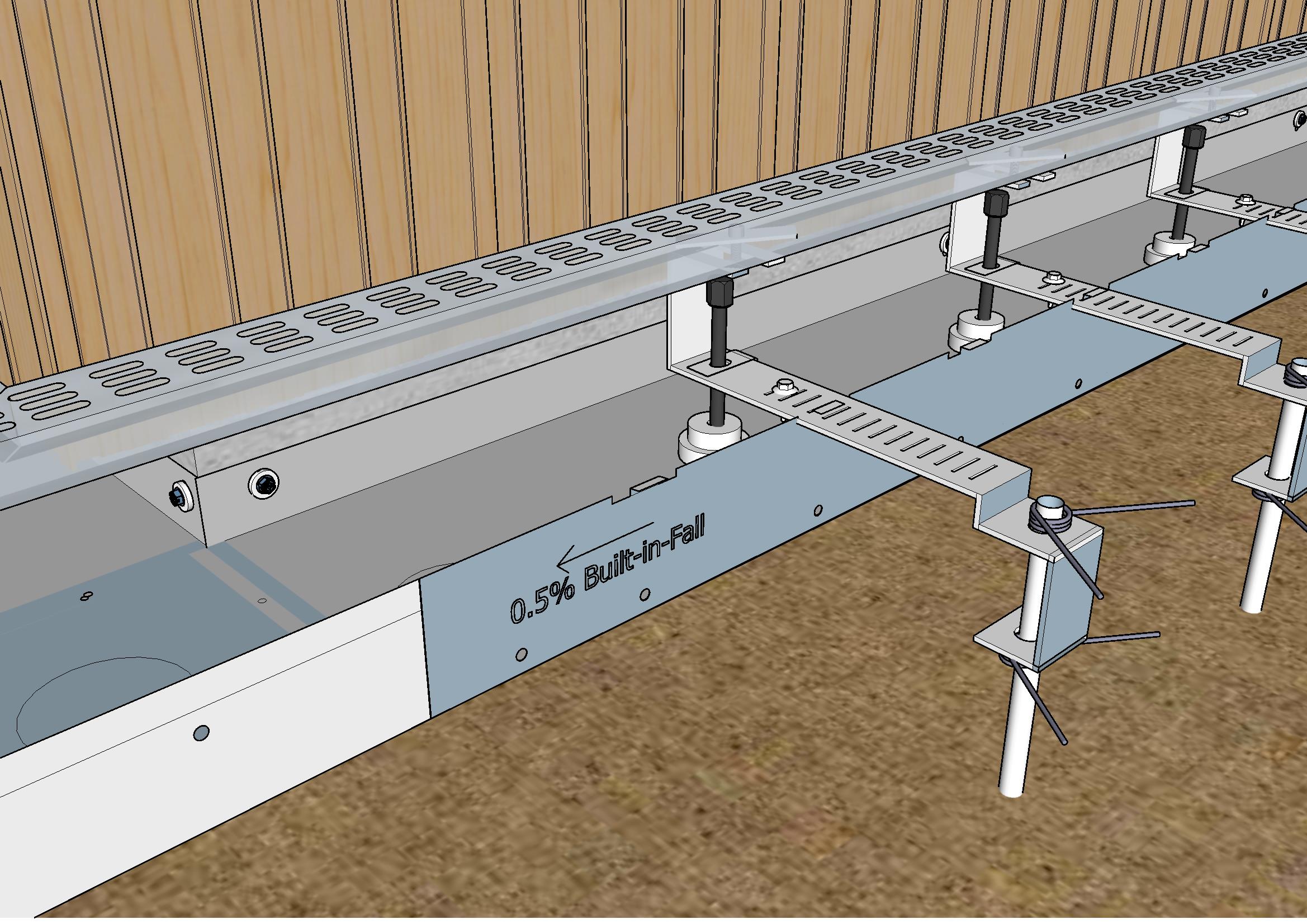
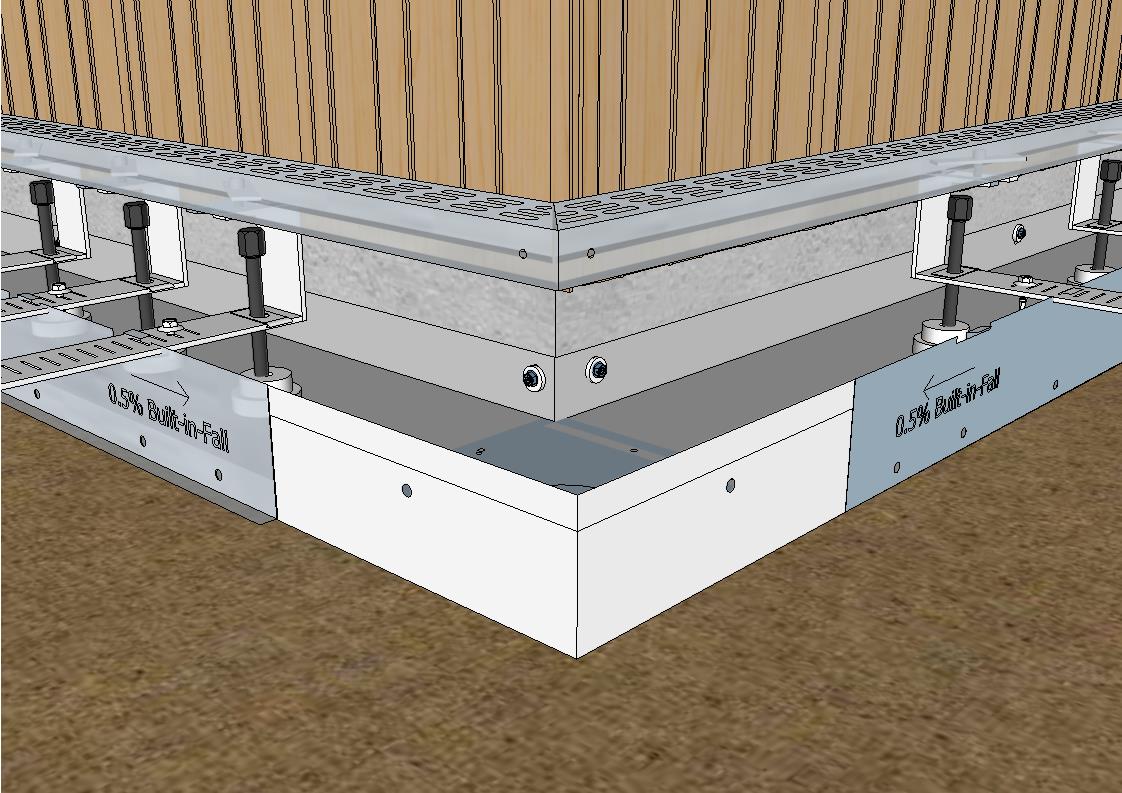
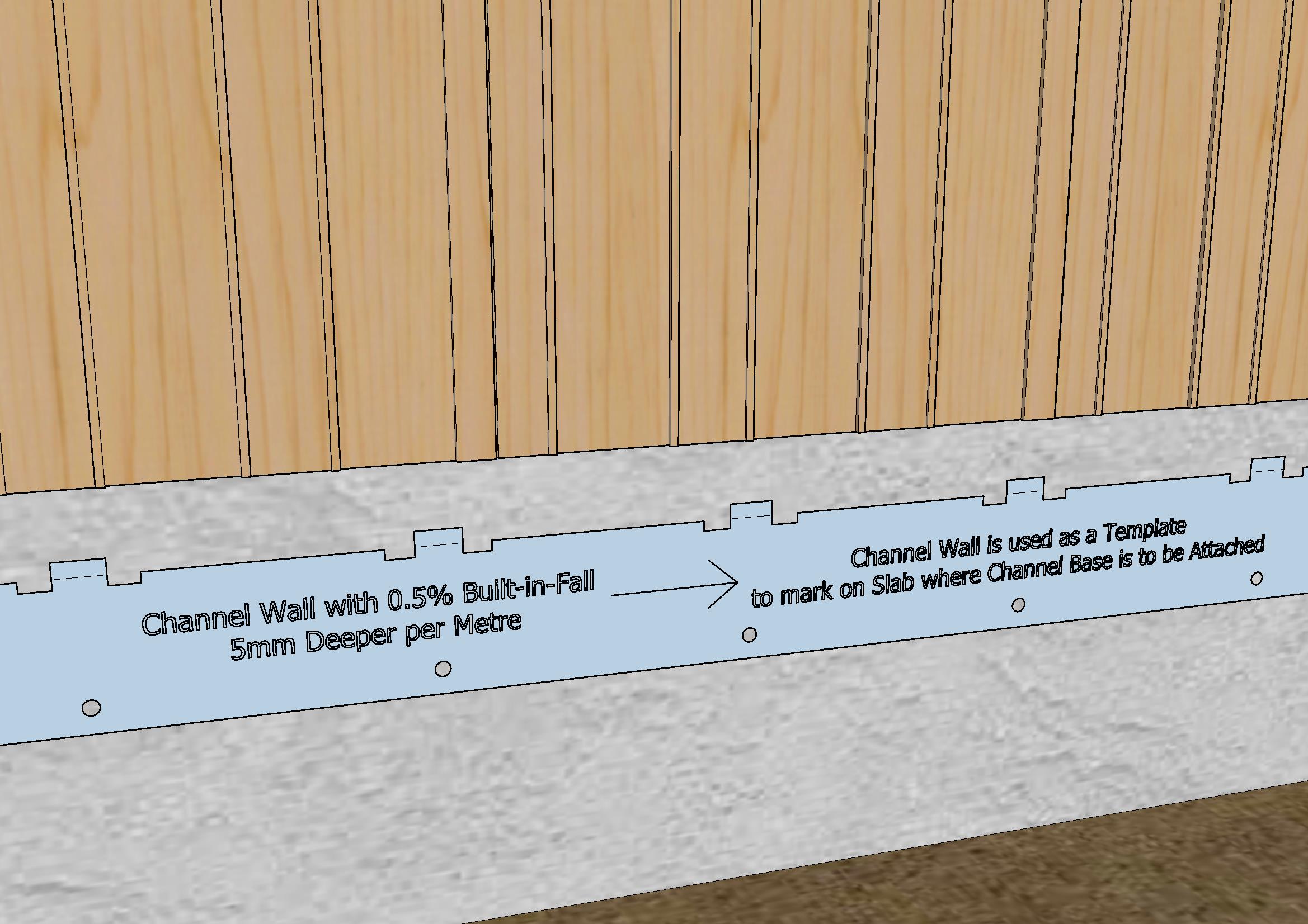
A Three Metre Length Modular System with Built-in-Fall
Thundaflo E2 is a stand-alone modular system can be completely installed before the concrete surround is poured.
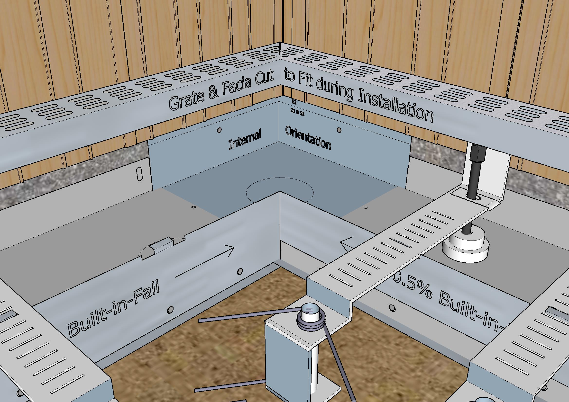
1:200 (0.5%) Built-in-Fall: No need to scree in fall.
Built-in-Fall Reversed by Rotating the Wall: R to L, L to R
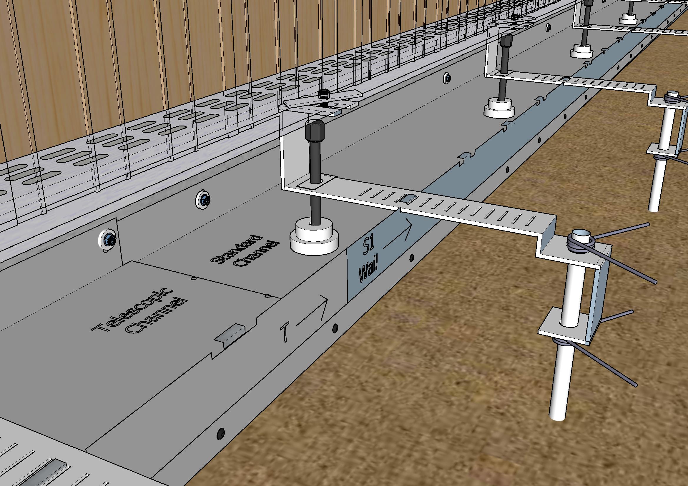
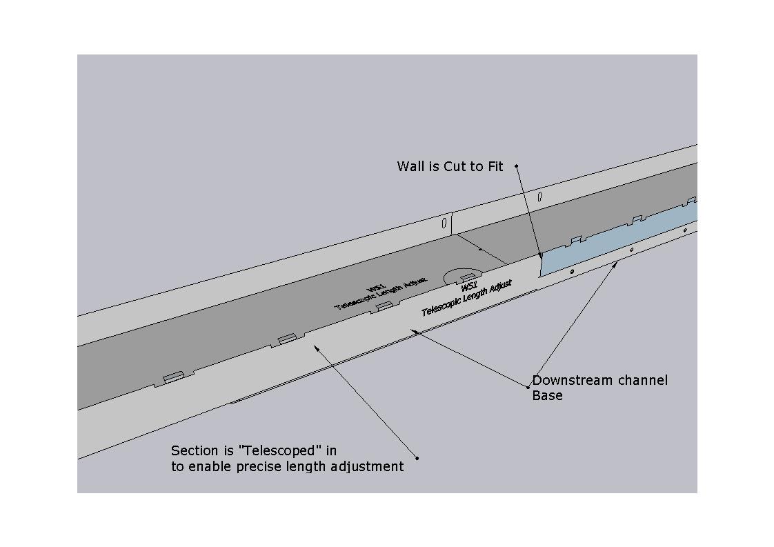
Section Lengths can be adjusted with a Telescopic Section
Cutting components to fit is kept to a minimum as section lengths can be adjusted with a telescopic section.
Channel Walls with Built-in-Fall can be used as Templates to Position System height against the concrete slab.
See Installation for more details.
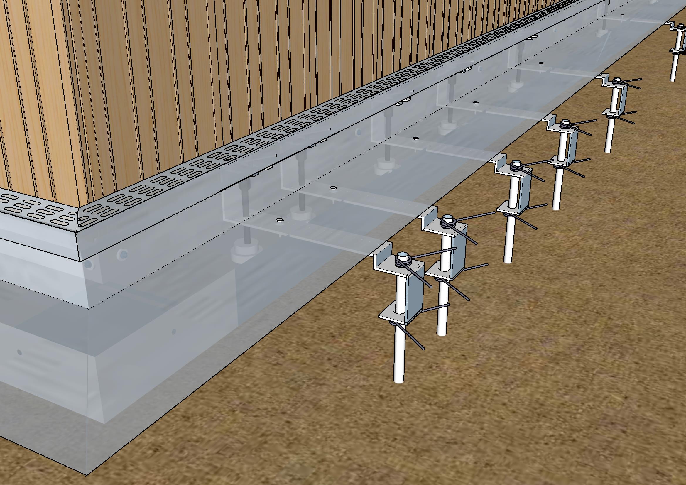
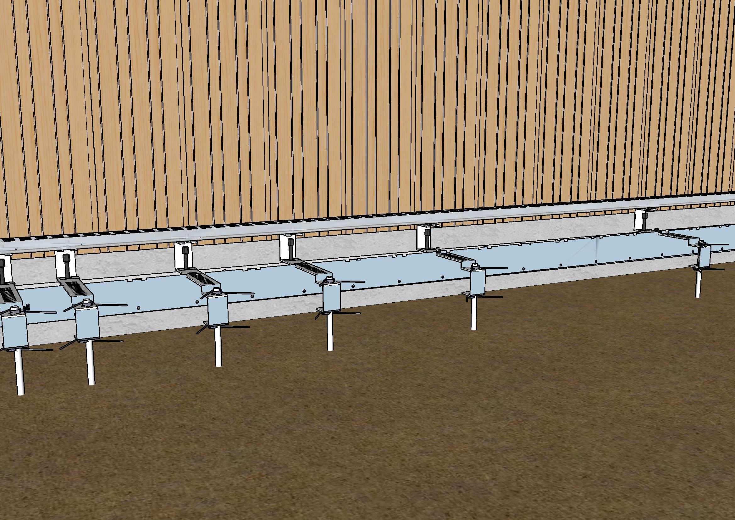
The Thundaflo Positioning System used to Adjust Height of Outside of Section
Fibreglass rods and torsion springs are used to position the height of outside of the Channel Section.
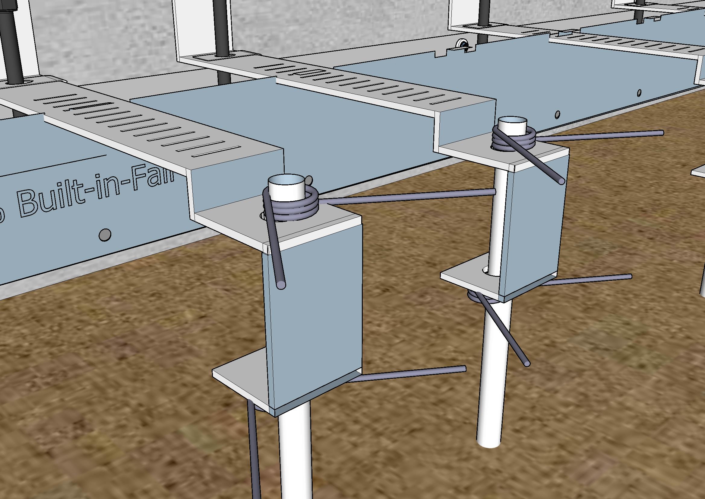
Maximum Load Bearing along a Section can be Adjusted by Varying the Spacing of Support Systems
125mm Spacing for high loading sections (vehicles/wheel chairs) to 750mm for virtually zero load sections (cats).
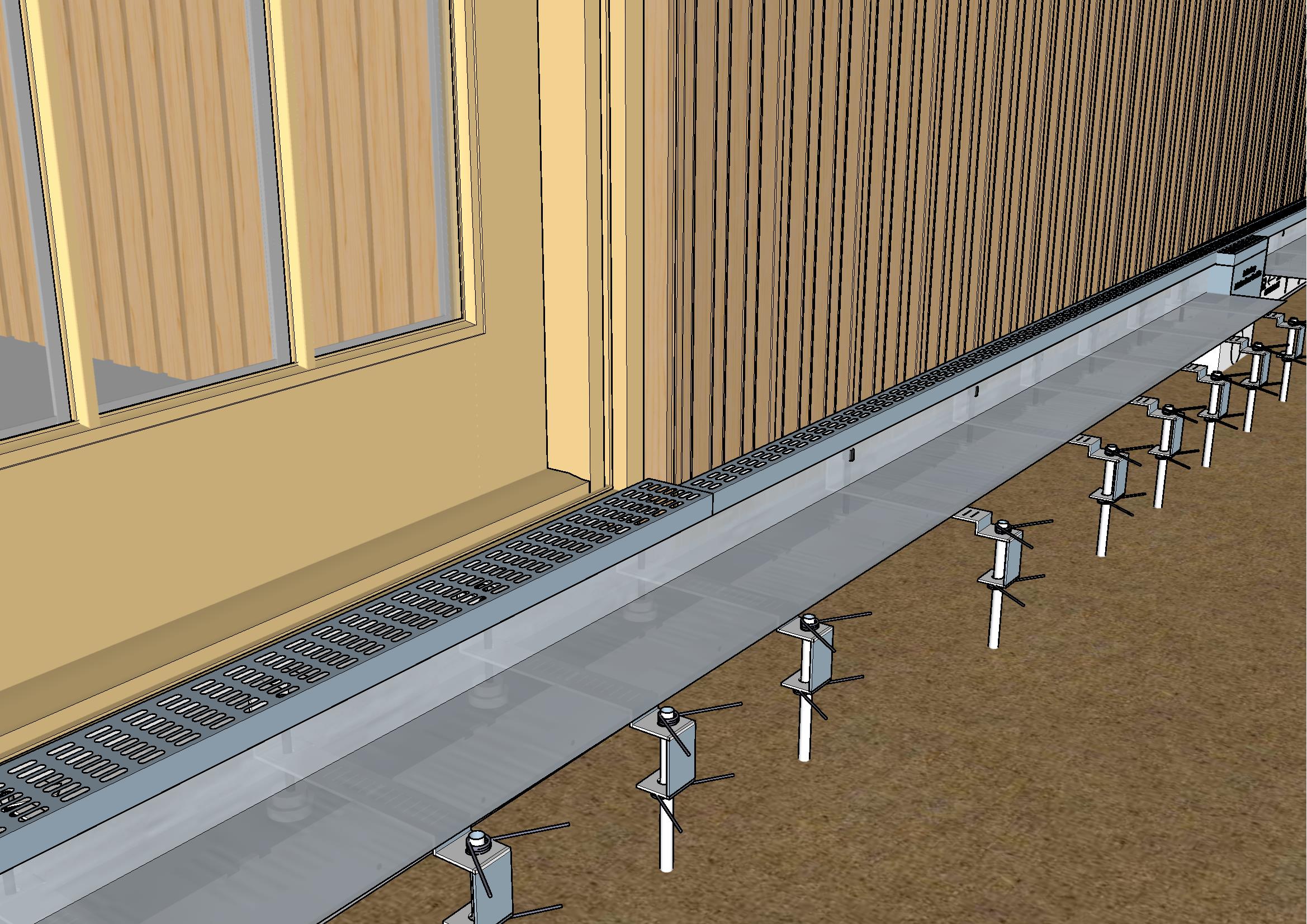
Width of Grating can Vary to Conform with a Varying Building Line
i.e. Variation in the building line between cladding and the door joinery.
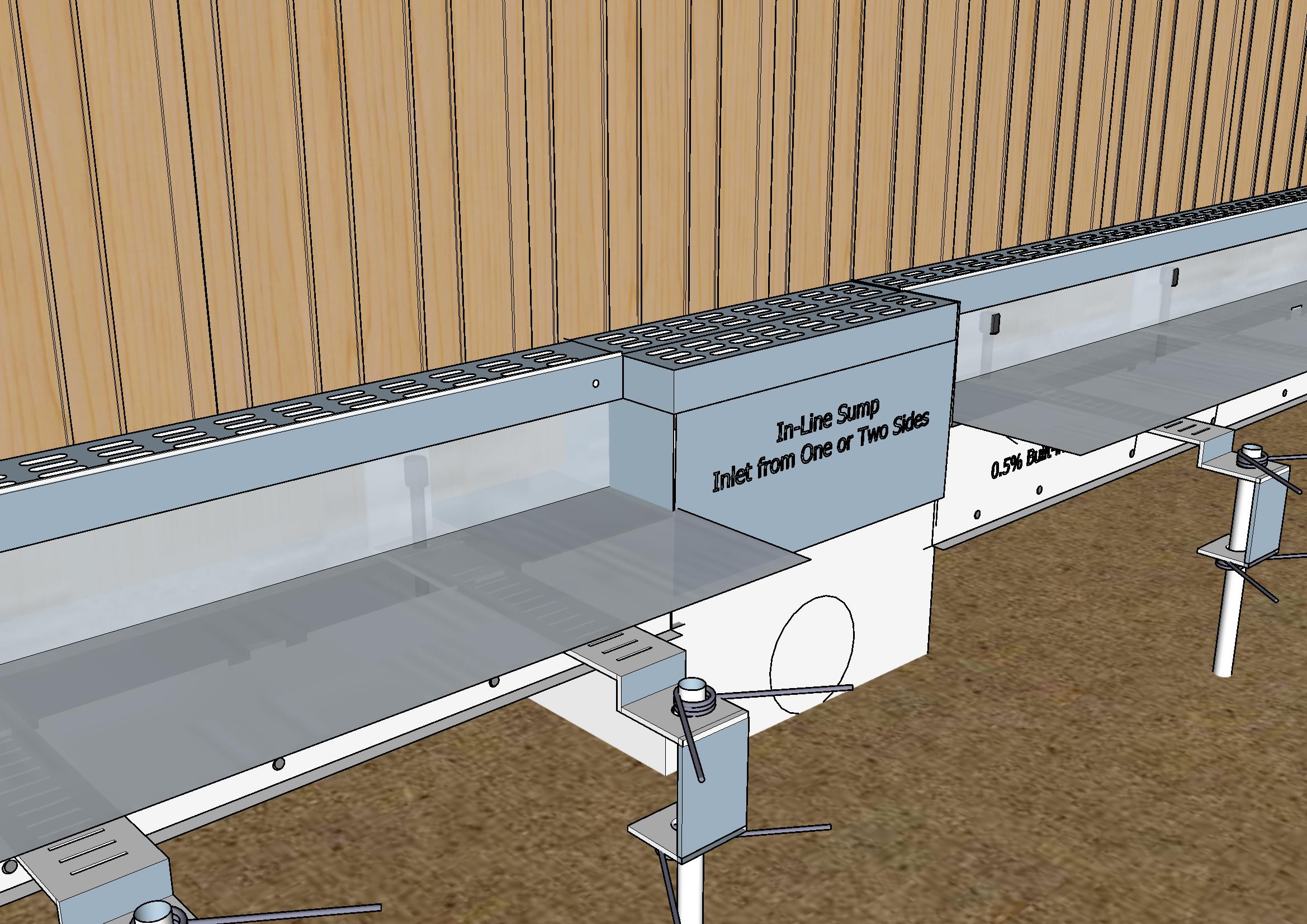
In-Line Sumps Provide Savings
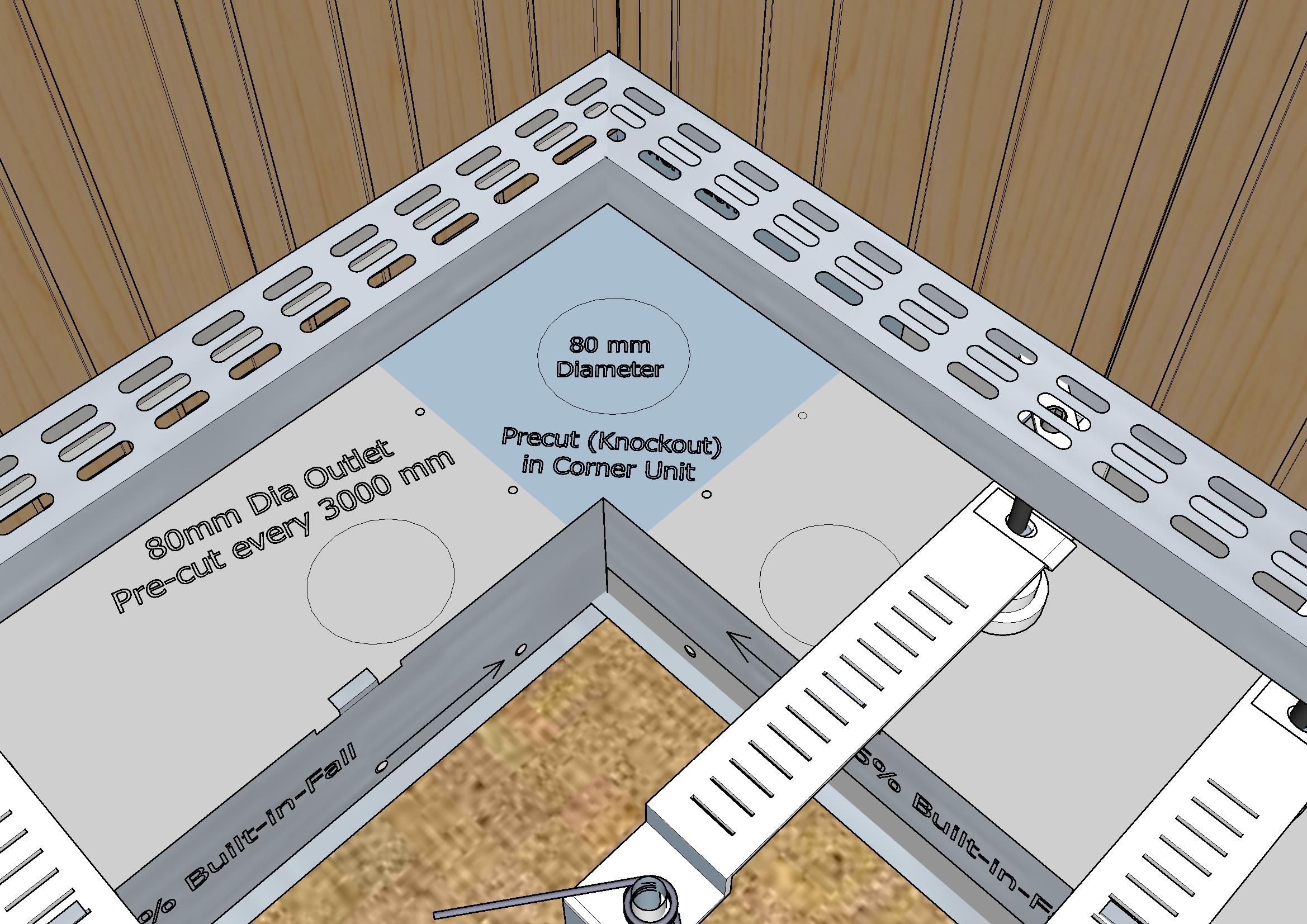
A 80mm outlet is precut and PVC flange is provided to connect outlet pipe.
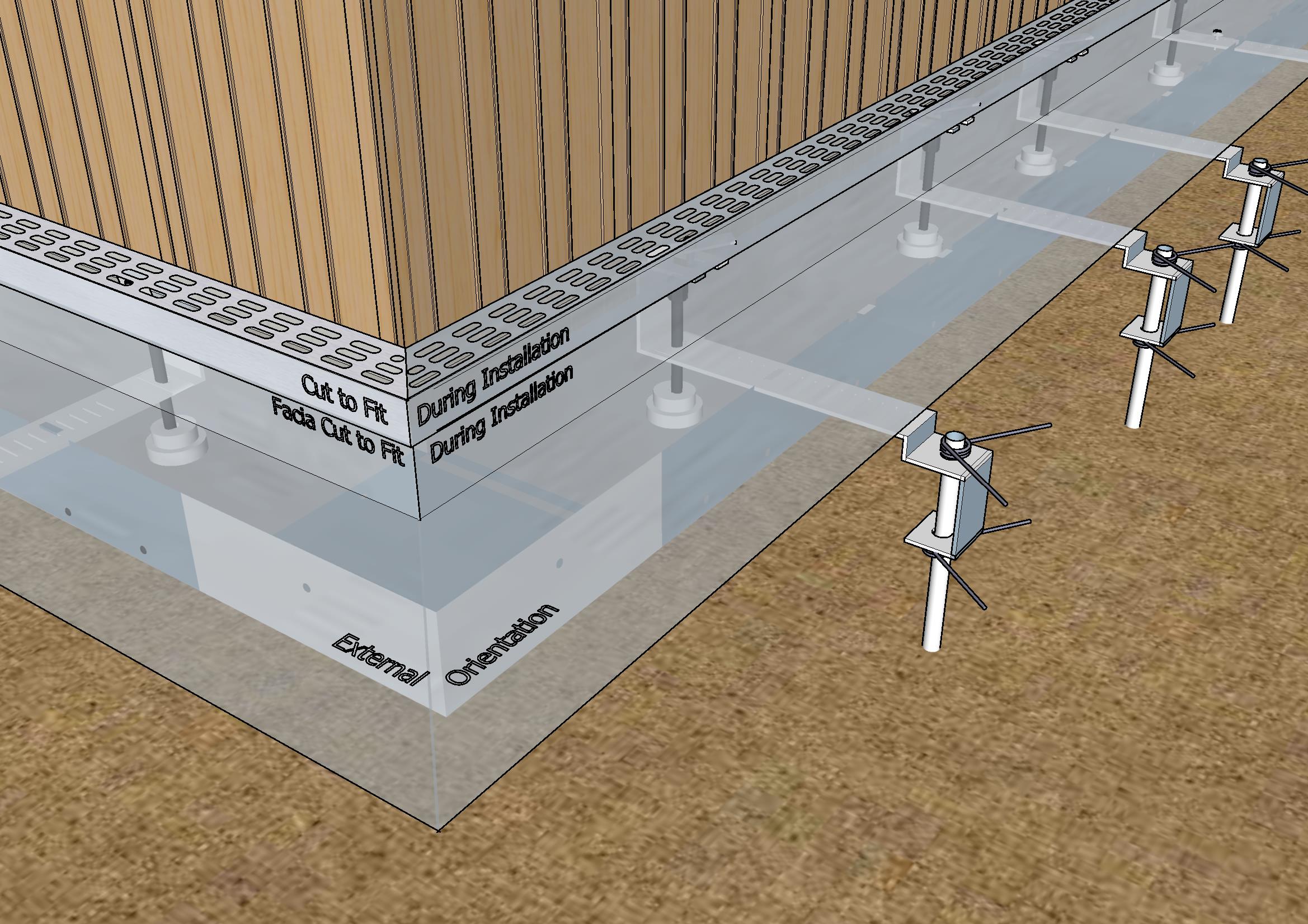
External Corner Unit
Internal Corner Unit
Outlets are pre-cut in Channel Sections and Corner Units
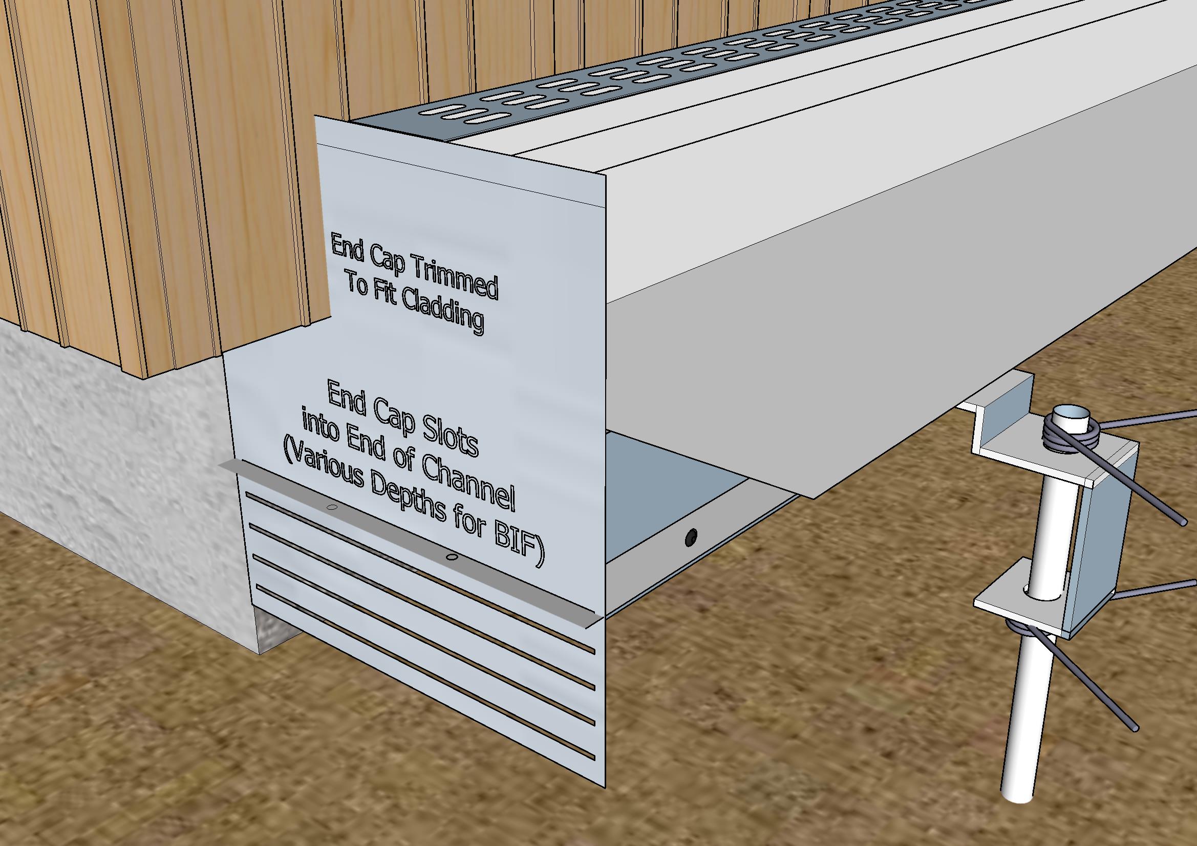
End Caps slot into Channel and cut to fit Building Profile
Telescoping Sections to Fit Section Length
N.Z. Pat. Appl. No. 809326